Legacy PCB Redesign: How to Modernize Obsolete Electronic Hardware
How to extend the life of proven electronic products by replacing obsolete components, recovering missing design information, improving manufacturability, and validating a modernized PCB without unnecessarily redesigning the entire system.
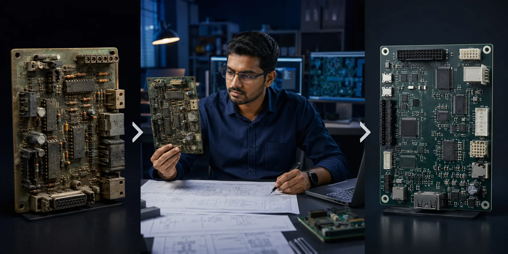
Legacy PCB redesign and modernization of obsolete electronic hardware
Many electronic products are designed to operate for years—or even decades.
Industrial controllers, instrumentation systems, automation equipment, transportation electronics, medical equipment and specialized hardware can remain commercially useful long after the components originally selected for the PCB have disappeared from the market.
That creates a difficult situation.
The product still works.
The customer still needs it.
The system around it may still be perfectly serviceable.
But the PCB may depend on components that are obsolete, discontinued, difficult to source or no longer supported.
At that point, organizations often face three broad choices:
IPC identifies redesign as one of several strategies for dealing with electronic component end-of-life, alongside approaches such as last-time buys and replacement through NPI.
The important point is that legacy PCB redesign does not automatically mean starting from scratch.
In many cases, the best solution is a controlled modernization that preserves as much of the proven architecture as possible while eliminating the sources of future risk.
1. What Is a Legacy PCB?
A legacy PCB is an electronic board associated with an established product or system whose design, components, manufacturing process or documentation may no longer align well with current production requirements.
The board itself does not necessarily need to be old.
A PCB can become "legacy" because:
This is why legacy electronics should be viewed as a product lifecycle challenge, not simply an age problem.
2. Why Legacy Electronics Become Difficult to Manufacture
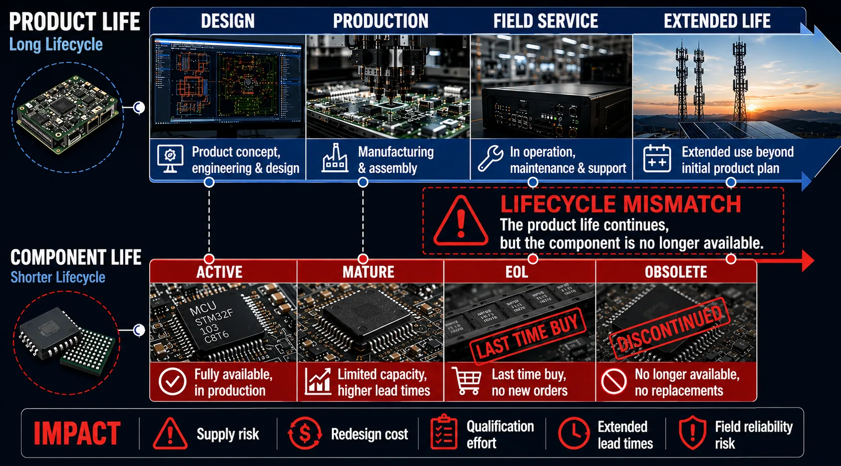
Legacy redesign often becomes necessary when the product lifecycle extends beyond the lifecycle of its electronic components.
Electronic products often have much longer useful lives than individual components.
A machine may remain in service for 15 years.
A specialized industrial system may be expected to operate even longer.
But semiconductor and electronic-component lifecycles can be considerably shorter.
This creates a lifecycle mismatch.
Product lifecycle
may continue →
Component lifecycle
may end.
Research on long-life electronic systems has specifically identified this mismatch between product lifecycles and component lifecycles as a major driver of redesign and sustainment costs.
The result is a familiar problem:
The product is not obsolete—but the parts needed to build it are.
3. The First Question Should Not Be "What Is the Replacement Part?"
This is one of the most important principles in legacy redesign.
When an IC becomes obsolete, it is tempting to immediately search for another component with:
But a datasheet-level similarity does not automatically make a component a safe replacement.
The replacement may differ in:
Therefore, the correct first question is:
What role does the original component perform in the complete system?
Only after that should replacement options be evaluated.
4. Start With a Legacy Design Audit
Before changing the PCB, establish what actually exists.
A legacy design audit may examine:
Hardware
Electrical design
Manufacturing
Product
This establishes the baseline before redesign begins.
5. What if the Original CAD Files Are Missing?
This is extremely common with legacy hardware.
The original organization may have:
That does not necessarily make modernization impossible.
The PCB itself can become an important engineering source.
This is where reverse engineering may be required.
6. PCB Reverse Engineering
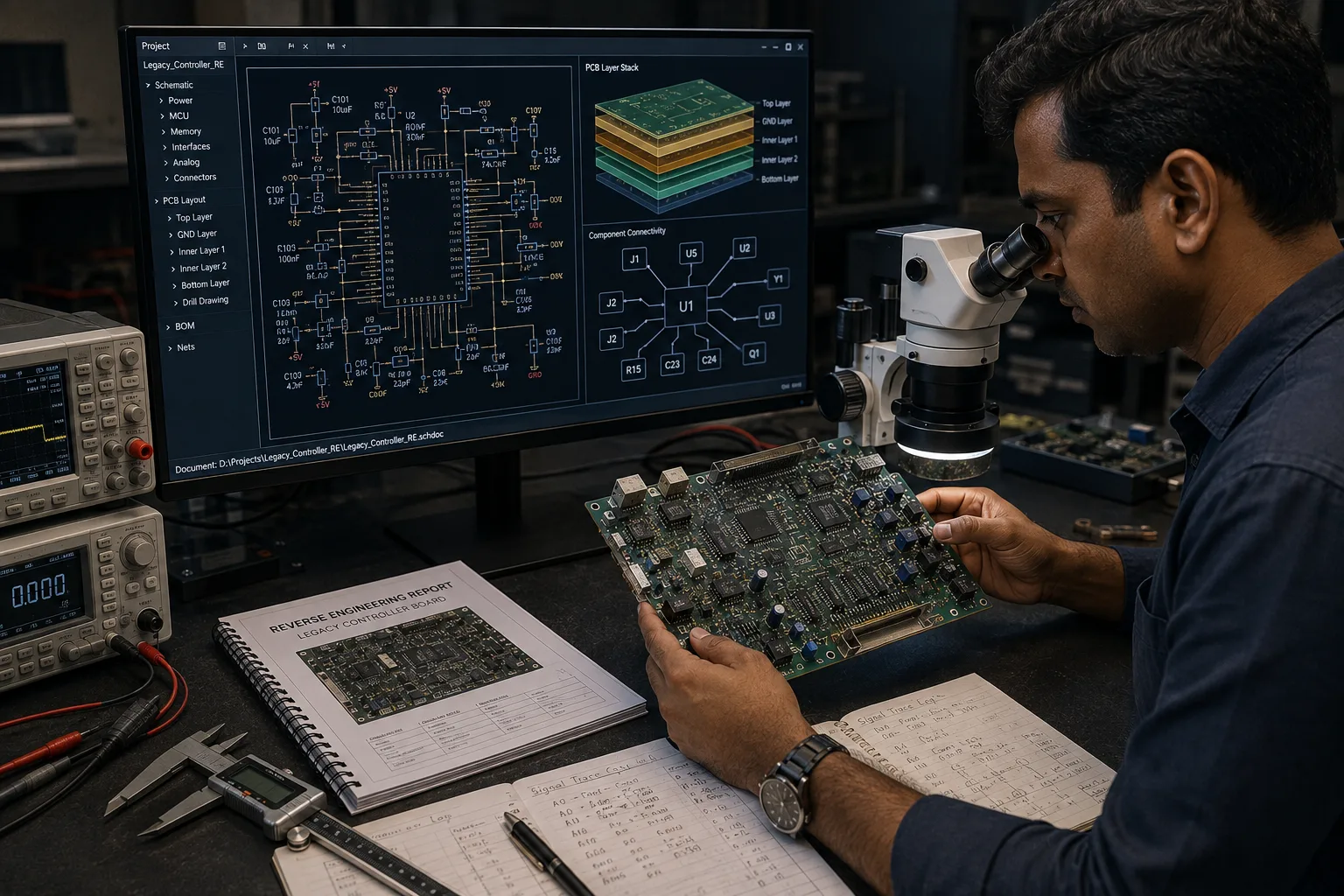
Reverse engineering can reconstruct the design baseline when original PCB documentation is incomplete or unavailable.
Reverse engineering a legacy PCB can involve reconstructing the information necessary to understand and reproduce the design.
Depending on the project, this can include:
The objective is not merely to redraw the board.
It is to establish a reliable engineering baseline.
IPC's guidance on legacy PCB replacement emphasizes the importance of establishing the original board's form, fit and function before making modifications.
7. Form, Fit and Function
One of the most important concepts in legacy PCB modernization is:
Form
Does the replacement board physically match the required dimensions, mounting points, connectors and interfaces?
Fit
Does it physically integrate with the existing equipment?
Function
Does it perform the required electrical and system functions?
A redesign that satisfies only the electrical requirements may still fail commercially if:
For many legacy systems, preserving form, fit and function can significantly reduce downstream integration risk. IPC specifically highlights this principle when reproducing replacement boards for interconnected legacy systems.
8. Exact Replica or Modernized Redesign?
This is a critical decision.
Not every legacy PCB should be redesigned aggressively.
There are two fundamentally different approaches.
Approach A — Functional Replication
Recreate the existing board as closely as practical.
This is appropriate when:
Approach B — Controlled Modernization
Retain the core architecture but update selected areas.
This may include:
The choice should be based on risk—not simply on what is technically possible.
9. Why "Improving Everything" Can Increase Risk
A legacy PCB may contain design characteristics that look outdated.
An engineer may be tempted to modernize:
all at once.
That can turn a targeted obsolescence problem into a completely new product-development project.
The more variables change simultaneously, the more difficult it becomes to determine why the redesigned product behaves differently.
For mature products, controlled change is often safer than maximum change.
IPC's legacy PCB guidance makes the same fundamental point: when exact replacement is required, even seemingly undesirable characteristics of the original board may affect electrical behavior and should not be changed casually.
10. Component Obsolescence Is Not Just a Procurement Problem
Suppose an obsolete regulator is replaced.
At first glance, this appears to be a purchasing issue.
But the replacement could affect:
Similarly, replacing a microcontroller may affect:
Therefore:
Component substitution can become a system-level engineering change.
11. Categorize Components Before Replacing Them
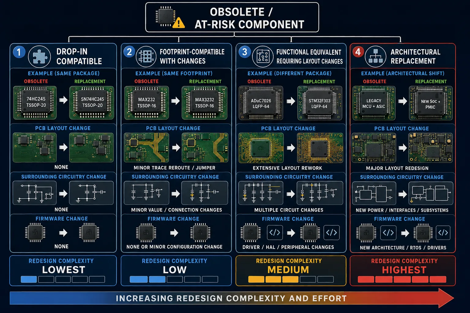
The redesign scope depends on how closely the replacement component matches the original electrical, mechanical and functional requirements.
A useful approach is to classify obsolete or risky components.
Category 1 — Drop-In Candidates
Same or highly compatible:
These generally represent the lowest redesign impact—but still require validation.
Category 2 — Footprint-Compatible Alternatives
The component may fit the existing footprint but have electrical differences requiring analysis.
Category 3 — Functionally Equivalent, Layout Changes Required
The replacement performs the required function but needs a new footprint or surrounding circuitry.
Category 4 — Architectural Replacement
The original component is so obsolete that the replacement requires changes to the surrounding circuit, firmware or architecture.
This classification helps determine the true redesign scope.
12. Evaluate the Entire Circuit Around the Component
A common mistake is to evaluate only the replacement component.
Instead, examine the surrounding circuit.
For example, changing a voltage regulator may require reviewing:
Likewise, replacing an analog IC may affect:
The component is part of a circuit—not an isolated object.
13. Firmware Can Be the Hidden Dependency
Legacy hardware modernization often focuses heavily on the PCB.
But firmware may be just as important.
A processor replacement may require:
The redesign project therefore needs to determine early whether the original firmware can remain unchanged.
If it cannot, firmware development and validation need to become part of the project scope.
14. Mechanical Compatibility Must Be Checked
A PCB redesign is not complete when the schematic works.
The redesigned board must also fit its physical environment.
Check:
This is particularly important for industrial equipment where the PCB may be tightly integrated into a mechanical assembly.
15. Don't Forget the PCB Material and Stack-Up
A legacy PCB may have a specific construction that contributes to its performance.
Consider:
If the redesign changes the stack-up unnecessarily, electrical characteristics can change.
For high-speed or sensitive circuits, this can affect:
The board should therefore be modernized with the required electrical behavior in mind—not simply redrawn using a current default fabrication stack.
16. DFM Can Be an Opportunity During Redesign
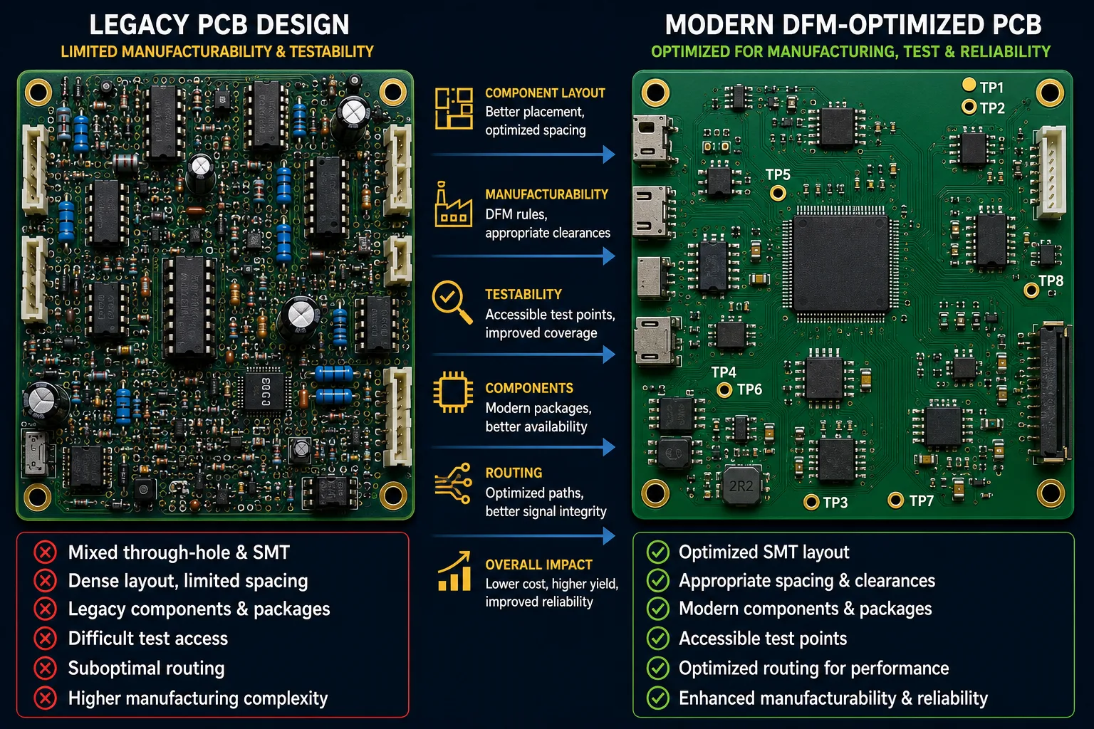
A controlled redesign can address both component obsolescence and manufacturing limitations.
Legacy designs frequently contain manufacturing compromises.
A redesign can provide an opportunity to improve:
This is where redesign can deliver value beyond solving obsolescence.
However, manufacturing improvements should still be controlled.
Every significant change should have a reason and validation plan.
17. What Documentation Should Be Created?
A modernized legacy PCB should not recreate the same documentation problem.
The redesigned product should ideally establish a controlled engineering baseline containing, as applicable:
This becomes extremely valuable for future production and maintenance.
18. BOM Reconstruction and Cleanup
The BOM deserves special attention.
Legacy BOMs may contain:
During redesign, the BOM should be reviewed for:
Availability
Can the part still be sourced?
Lifecycle
Is the component active, mature or approaching EOL?
Sourcing
Are there credible supply options?
Specification
Does it actually meet the design requirement?
Package
Does the package remain suitable?
Alternate
Can a qualified alternate be identified?
This is where engineering and supply-chain analysis need to work together.
19. Build Obsolescence Resistance Into the New Design
The goal should not be to solve today's obsolete component problem only to create another one several years later.
A modernized design should consider:
Proactive BOM monitoring and pre-qualified alternates are increasingly recognized as important elements of electronics obsolescence management.
20. Validation Is the Most Important Stage
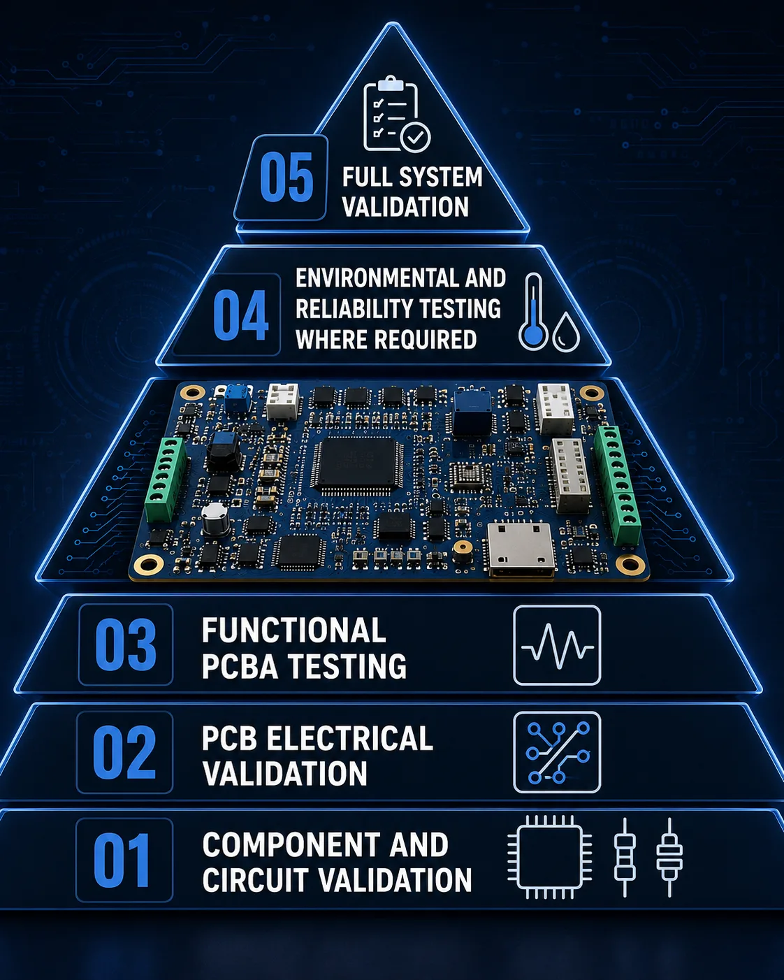
Legacy redesign validation should progress from circuit-level verification toward complete system-level confirmation.
A redesigned PCB should not be considered production-ready simply because:
Validation should demonstrate that the revised board meets its intended requirements.
Depending on the product, this may include:
Electrical validation
Functional validation
Environmental validation
Where applicable:
EMC/EMI
Where required by the product and regulatory environment.
System validation
Does the new PCB actually work inside the original system?
21. Prototype Builds Are Essential
Before production release, the redesigned PCB should normally go through prototype or pilot builds appropriate to the program's risk.
The prototype can reveal:
This is much less expensive to discover during engineering validation than after volume production.
22. Compare the New Board With the Original
For a legacy product, one of the most useful validation techniques is direct comparison.
Where practical, compare:
Electrical
Functional
Mechanical
Thermal
The original functioning board can serve as a valuable baseline.
23. What If the Original Board Has Known Defects?
This creates an interesting engineering decision.
Suppose the original PCB contains:
Should the redesign remove it?
Not automatically.
If the objective is functional replication, the modification may need to be preserved or carefully analyzed.
If the objective is controlled modernization, it may be possible to eliminate it—but only after understanding why it existed.
The principle is:
Do not remove a legacy feature simply because it looks wrong. Determine what function it performs first.
24. Should You Redesign the Entire PCB?
Not necessarily.
A targeted redesign may be preferable when:
A broader redesign may be justified when:
The right answer is therefore project-specific.
25. Legacy PCB Redesign vs Last-Time Buy
A last-time buy can be attractive when:
Redesign becomes more attractive when:
IPC identifies both last-time buying and redesign among the strategies available for managing component end-of-life.
The decision should be based on total lifecycle economics, not simply today's component price.
26. The True Cost of Legacy Obsolescence
The cost of an obsolete PCB is not limited to the component itself.
Consider:
Component premium
Broker sourcing risk
Inventory carrying cost
Production disruption
Engineering time
Repair cost
Field-support cost
Potential redesign cost
Qualification cost
The cheapest short-term option may therefore become the most expensive long-term strategy.
27. Common Legacy PCB Redesign Mistakes
Mistake 1 — Treating component replacement as a purchasing exercise
The replacement must be evaluated within the complete circuit.
Mistake 2 — Redesigning too much
Unnecessary changes increase validation risk.
Mistake 3 — Redesigning too little
A replacement component may require changes elsewhere.
Mistake 4 — Ignoring firmware
Processor and interface changes may require software changes.
Mistake 5 — Ignoring mechanics
A functioning PCB is useless if it does not fit the equipment.
Mistake 6 — Recreating the board without recovering the design intent
A physical copy without understanding the circuit can make future engineering difficult.
Mistake 7 — Ignoring manufacturing
A technically correct PCB can still be unnecessarily expensive or difficult to assemble.
Mistake 8 — Skipping system validation
Board-level success does not guarantee system-level compatibility.
Mistake 9 — Failing to document the new design
This simply recreates the legacy problem for the next engineering team.
Mistake 10 — Waiting until the component is completely unavailable
By then, the redesign may be urgent rather than strategic.
28. A Better Legacy PCB Redesign Workflow
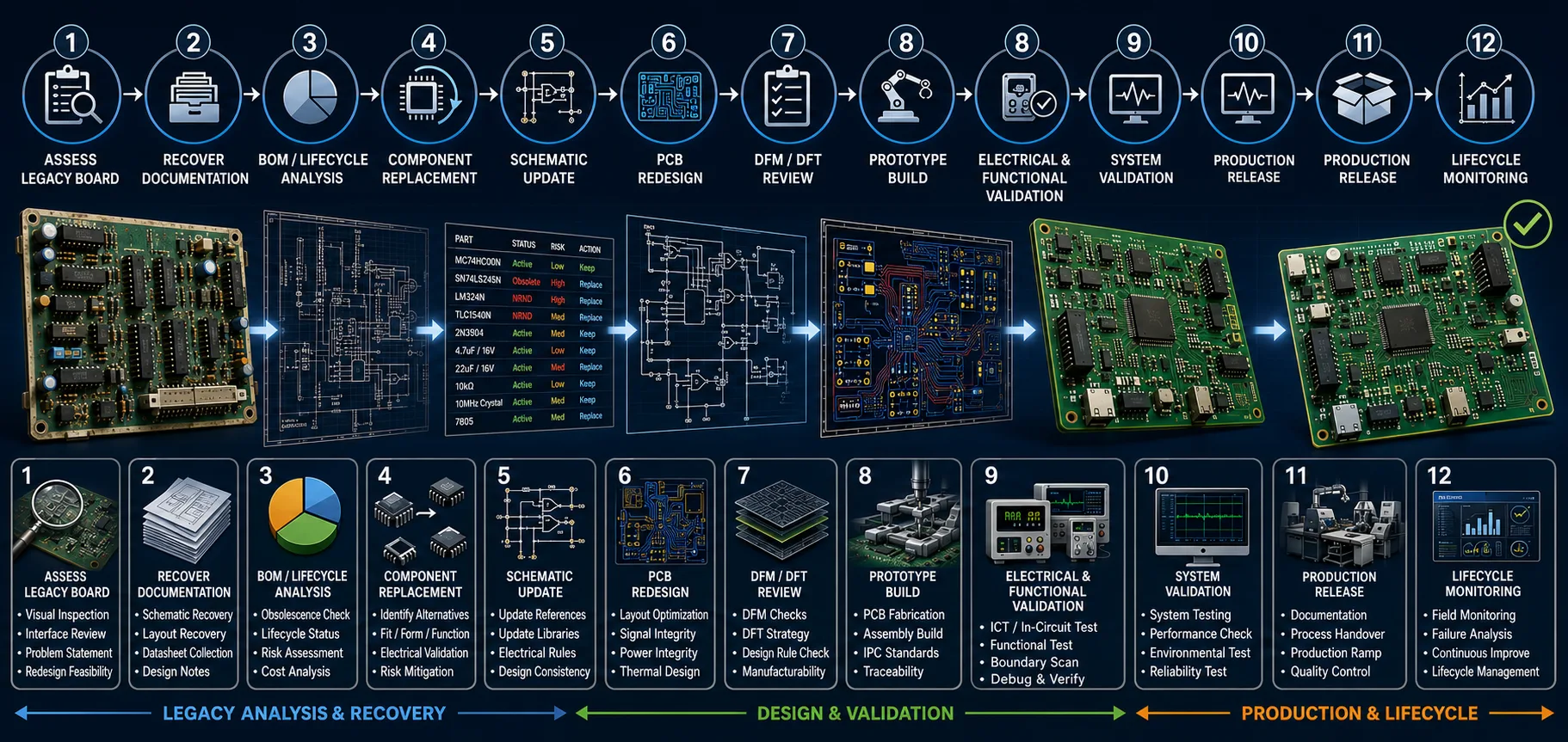
A structured legacy PCB redesign process reduces unnecessary changes while creating a production-ready modern design.
A disciplined project can follow this sequence:
1. Identify the lifecycle problem
↓
2. Freeze and document the existing baseline
↓
3. Collect available technical documentation
↓
4. Reverse engineer missing information where required
↓
5. Analyze the BOM and component lifecycle
↓
6. Classify obsolete components
↓
7. Evaluate replacement options
↓
8. Define redesign scope
↓
9. Update schematic
↓
10. Update PCB layout
↓
11. Review DFM/DFT
↓
12. Build prototypes
↓
13. Perform electrical and functional validation
↓
14. Validate system compatibility
↓
15. Complete required qualification
↓
16. Release production documentation
↓
17. Establish lifecycle monitoring
29. Designing for the Next Product Lifecycle
A successful redesign should leave the product in a better position than before.
That means considering:
Component longevity
Prefer components with credible long-term availability.
Alternate sourcing
Where practical, reduce unnecessary single-source dependency.
Documentation
Maintain controlled engineering data.
Testability
Provide appropriate test access.
Manufacturability
Design around current production capabilities.
Lifecycle monitoring
Monitor component status after redesign.
Change management
Control future revisions through formal engineering change processes.
This turns redesign from a one-time emergency into part of product lifecycle management.
30. Why the Manufacturing Partner Matters
Legacy redesign sits at the intersection of:
Engineering
Procurement
PCB fabrication
PCBA assembly
Testing
Quality
Product lifecycle management
That makes the choice of partner particularly important.
A CAD-only provider may be able to redraw the PCB.
A component distributor may be able to suggest alternatives.
A PCB manufacturer may be able to fabricate the board.
But the project can benefit considerably from a partner that understands how those pieces interact.
The most useful partner is one capable of connecting:
Redesign → Component sourcing → PCB fabrication → PCBA → Testing → Production
31. What International Buyers Should Look For
When selecting a manufacturing partner for legacy electronics modernization, ask:
Engineering capability
Supply chain
Manufacturing
Testing
Production
These questions help determine whether the supplier is capable of supporting the whole lifecycle, rather than just one stage.
32. A Practical Legacy PCB Redesign Checklist
Existing Design
Obsolescence
Redesign
Validation
Production
33. The Strategic Question: Repair, Replicate or Redesign?
Legacy hardware can often be approached through repair, replication or controlled redesign depending on lifecycle and technical requirements.
When a legacy PCB becomes difficult to support, the decision can often be framed around three paths:
Repair
Keep the existing design and replace failed components where possible.
Replicate
Recreate the original PCB so the existing system can continue operating.
Redesign
Modernize selected portions—or the complete board—to address obsolescence, manufacturability, performance or lifecycle risk.
There is no universally correct option.
The right answer depends on:
34. Modernization Does Not Mean Starting Over
This is perhaps the most important message for organizations managing legacy hardware.
A successful redesign does not necessarily mean:
"Throw away the old design and create a new product."
It can mean:
"Preserve what has already been proven, change what has become unsustainable, and validate the new design systematically."
That approach can reduce unnecessary engineering effort while extending the useful life of a mature product.
35. FINAL TAKEAWAY
Legacy electronic hardware does not necessarily need to be abandoned simply because its original PCB components are no longer available.
A disciplined legacy PCB redesign can provide a path forward by:
The key is to control the scope of change.
A legacy PCB that has successfully operated in the field for years contains valuable engineering knowledge. The goal should be to preserve that proven behavior wherever practical while removing the dependencies that threaten future production
36. QUADRIONIX PERSPECTIVE
At QUADRIONIX, legacy electronics modernization is approached as more than a PCB redraw.
The objective is to connect the engineering and manufacturing decisions required to take a mature electronic product from an existing, potentially obsolete design toward a repeatable and supportable production platform.
That can involve:
Legacy PCB Assessment
→ Reverse Engineering Where Required
→ BOM & Obsolescence Analysis
→ Component Alternate Evaluation
→ Schematic & PCB Redesign
→ DFM/DFT Review
→ Prototype & NPI
→ PCB/PCBA Manufacturing
→ Functional Testing
→ Production
For international OEMs and product companies, this integrated approach can help reduce the number of separate handoffs between engineering, sourcing, PCB fabrication, assembly and testing.
QUADRIONIX can help evaluate a practical path from legacy hardware to a modern, manufacturable and supportable PCBA.
Preserve what works. Modernize what doesn't. Manufacture for the next lifecycle
Frequently Asked Questions
Ready to manufacture your electronics project?
Upload your Gerber files & BOM for automated DFM review, engineering feedback, and guaranteed delivery timelines.