SMT vs THT: When to Use What
A Practical Engineering Guide to Surface-Mount and Through-Hole Assembly, Component Selection, Manufacturing Trade-Offs and Design-for-Assembly Decisions
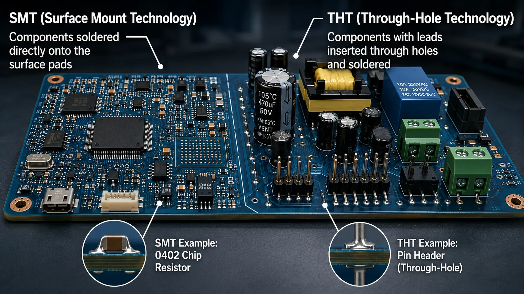
SMT vs THT: When to Use What
Introduction
Choosing between Surface Mount Technology (SMT) and Through-Hole Technology (THT) is not simply a question of which assembly method is newer.
In modern electronics manufacturing, SMT is the dominant technology for many electronic assemblies because it enables high component density, automated placement and compact PCB designs.
But THT remains highly relevant.
Connectors, large mechanical components, transformers, relays, high-stress interfaces and certain power components may still benefit from through-hole construction.
And many real-world PCBAs use both technologies on the same board.
This is known as:
Mixed-technology assembly
The engineering decision should therefore not be:
SMT vs THT — which one is better?
It should be:
Which assembly technology is appropriate for each component and for the overall product?
That decision affects:
Understanding those trade-offs before PCB layout is therefore an important part of Design for Manufacturing and Design for Assembly.
1. What Is SMT?
Surface Mount Technology (SMT) is an assembly method in which components are mounted directly onto conductive pads on the surface of the PCB.
Unlike through-hole components, SMT components generally do not require leads to pass through the PCB.
Typical SMT components include:
The process is highly compatible with automated PCB assembly.
A typical SMT process can include:
Solder paste printing
↓
Solder paste inspection
↓
Pick-and-place
↓
Reflow soldering
↓
AOI
↓
X-ray where required
↓
Functional or electrical testing
2. What Is THT?
Through-Hole Technology (THT) uses components with leads that pass through drilled holes in the PCB.
The component leads are inserted through the board and soldered to pads associated with those holes.
Typical THT components include:
THT assembly can be performed manually or through automated processes such as:
3. SMT vs THT — The Fundamental Difference
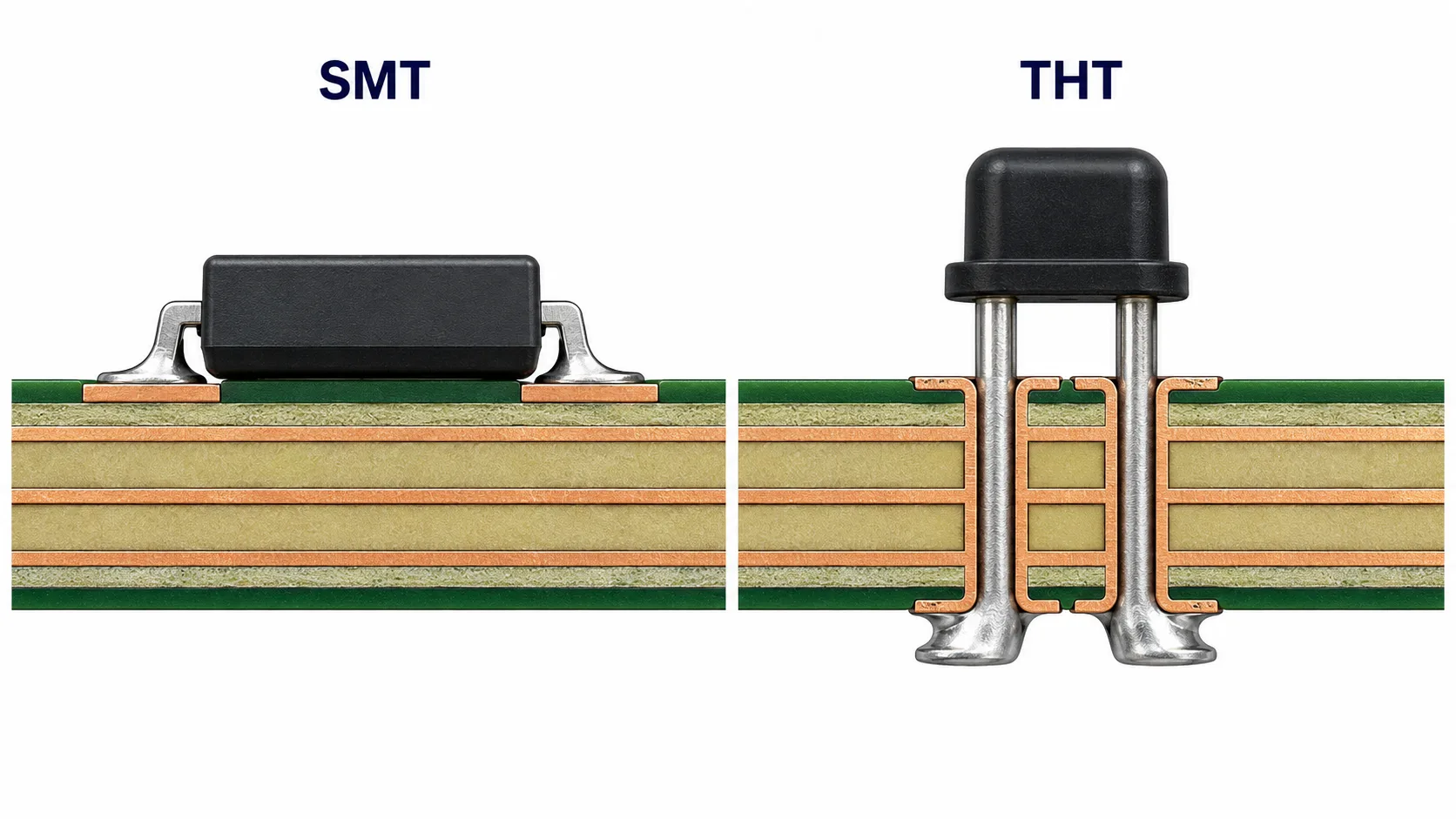
The basic construction difference is straightforward.
SMT
Component:
↓
PCB surface pad
The component is mounted directly on the board surface.
THT
Component lead:
↓
PCB hole
↓
Soldered connection
The component mechanically penetrates the PCB.
This difference has major consequences for PCB layout, component density, mechanical strength and manufacturing processes.
4. Why SMT Became Dominant
Modern electronics require:
SMT addresses many of these requirements.
Because components are mounted on the PCB surface, both sides of the board can potentially be populated.
This enables significantly higher component density than would generally be practical using only through-hole components.
5. SMT Enables High Component Density
Consider two boards with the same electrical functionality.
A through-hole-only implementation may require substantial board area because component bodies and leads need to accommodate drilled holes and mechanical clearances.
An SMT implementation can place components much closer together.
This is particularly important for:
Small package sizes also allow engineers to reduce PCB area where electrical and manufacturing constraints permit.
6. SMT Component Packages
SMT is not one component size.
Packages range from relatively large devices to extremely small passives.
Examples include:
0402
0603
0805
1206
for passive components, and:
for semiconductor and specialized components.
Smaller packages provide greater density but introduce additional manufacturing considerations.
These include:
Therefore:
The smallest package is not automatically the best package.
7. THT's Main Advantage: Mechanical Robustness
Through-hole components have an important physical advantage.
The leads passing through the PCB provide mechanical anchoring.
This can be valuable where a component experiences:
Examples include:
A connector that is repeatedly plugged and unplugged can impose substantial mechanical stress on its solder joints.
Through-hole construction can provide additional mechanical retention.
8. Why Connectors Often Remain Through-Hole
Connectors are one of the clearest examples of where THT can remain advantageous.
Consider a board-mounted connector.
The user may:
That mechanical force transfers into the connector and PCB.
A through-hole connector can use its leads and mounting structure to provide stronger mechanical attachment.
Some connectors are therefore available in:
The correct selection depends on the mechanical requirements of the application.
9. SMT vs THT Manufacturing Process
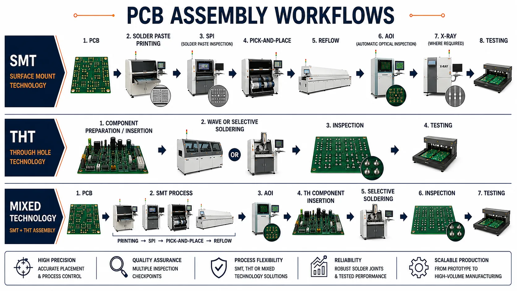
A simplified SMT manufacturing flow is:
PCB
↓
Solder paste printing
↓
SPI
↓
Component placement
↓
Reflow
↓
AOI
↓
X-ray where required
↓
Testing
THT may involve:
Component insertion
↓
Lead forming/cutting where required
↓
Wave/selective soldering or manual soldering
↓
Inspection
↓
Testing
Mixed-technology boards may require a combination of these processes.
10. SMT and Reflow Soldering
Most automated SMT assembly uses reflow soldering.
Solder paste is deposited onto PCB pads.
Components are placed into the solder paste.
The assembly then passes through a controlled thermal profile.
The solder paste melts and forms solder joints between the component terminals and PCB pads.
The thermal profile must be appropriate for:
Poor process control can contribute to defects such as:
These issues are discussed in greater detail in our article on common PCB assembly issues.
11. THT and Wave Soldering
For suitable THT assemblies, wave soldering can provide efficient soldering of multiple through-hole joints.
The underside of the PCB passes across a controlled solder wave.
The solder contacts exposed leads and pads and forms the solder joints.
However, not every THT assembly is suitable for conventional wave soldering.
Component geometry, thermal sensitivity, board configuration and solder-access conditions all matter.
12. Selective Soldering
Selective soldering is particularly useful for mixed-technology boards where certain THT components must be soldered after SMT reflow.
The machine applies solder to selected through-hole locations rather than exposing the entire PCB underside to a solder wave.
This can provide better process control for boards containing:
The process sequence can therefore be designed around the actual assembly architecture.
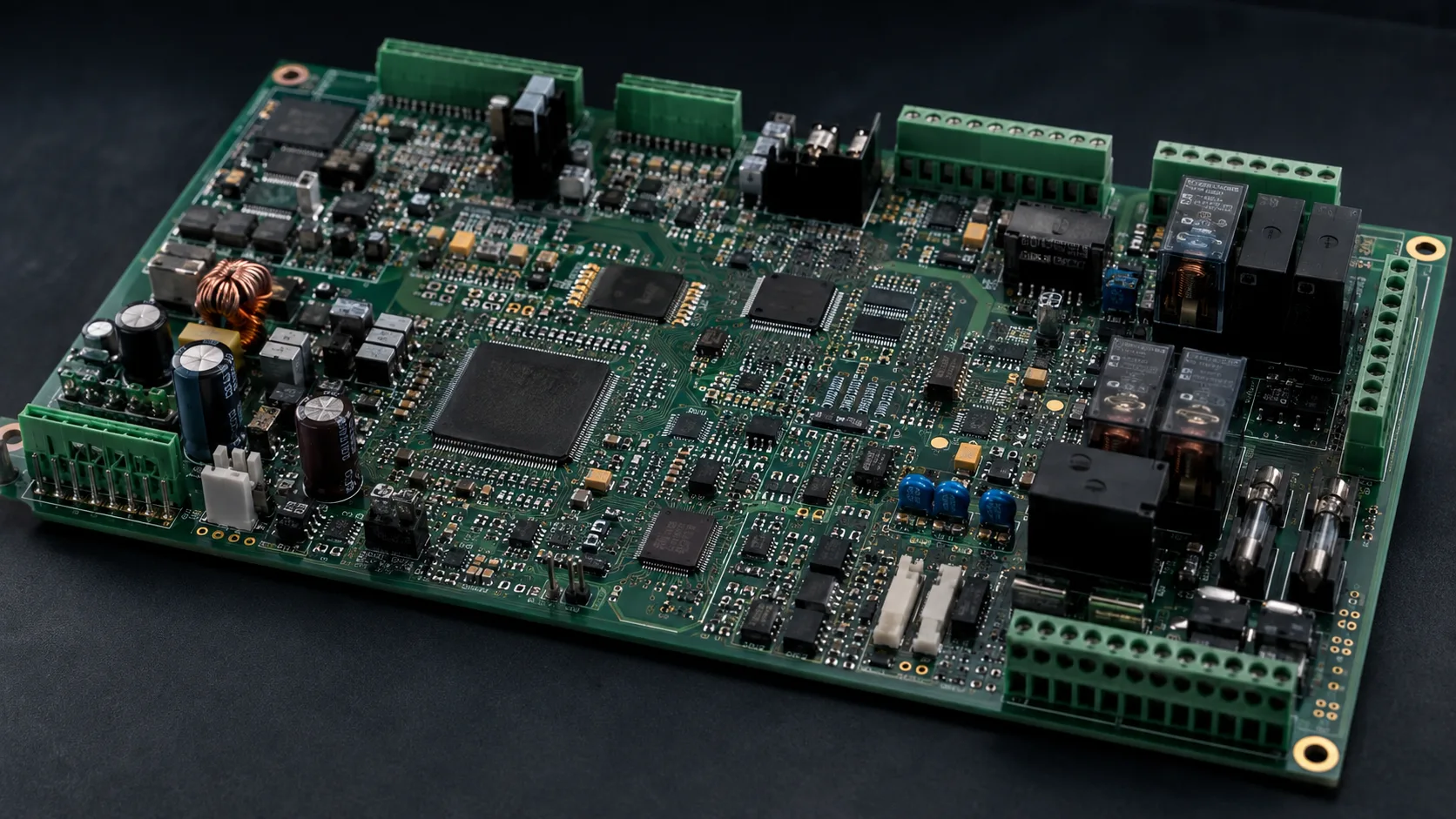
13. Mixed Technology: The Practical Reality
Many modern PCBAs are neither purely SMT nor purely THT.
A typical industrial controller might contain:
SMT
THT
This is a mixed-technology PCBA.
The manufacturing challenge becomes coordinating the two assembly technologies without creating unnecessary process complexity.
14. SMT vs THT: Cost Considerations
Cost comparisons can become misleading when reduced to:
“SMT is cheaper.”
or:
“THT is cheaper.”
The actual cost depends on:
For high-volume production, SMT's automation and placement density can provide substantial manufacturing advantages.
For low-volume or highly specialized assemblies, the economics can be different.
15. Why Component Count Matters
An SMT line can place large numbers of components automatically.
The economic advantage becomes stronger as the production volume increases.
However, every component still creates manufacturing requirements.
For example:
Reducing unnecessary component variety can therefore simplify manufacturing.
This is one reason BOM optimization and DFM should be considered alongside assembly technology.
16. Package Standardization Can Reduce Complexity
Suppose a PCB uses:
The design may be electrically valid.
But where practical, standardizing package families can simplify:
For example, using a common passive package size across suitable circuits can reduce manufacturing complexity.
However, electrical, thermal and mechanical requirements should always take precedence.
17. THT and PCB Real Estate
Through-hole components require drilled holes.
Those holes consume PCB real estate and can affect routing.
A dense THT design may require:
This becomes particularly important in multilayer high-density boards.
SMT can provide greater routing flexibility because components are mounted on the surface rather than occupying through-board holes.
18. THT Holes Can Affect Routing
A plated through-hole creates an electrical structure extending through the PCB.
Depending on its function, it can interact with:
For high-density boards, unnecessary through-hole features can therefore complicate layout.
This is one reason modern high-density designs generally rely heavily on SMT.
19. Thermal Considerations
Component technology also interacts with thermal design.
Large power components may require:
A THT package may be advantageous for certain power or mechanically demanding components.
But SMT packages can also provide excellent thermal performance when designed correctly.
For example, exposed-pad packages can transfer heat through:
Component
↓
Thermal pad
↓
PCB copper
↓
Thermal vias
↓
Internal/thermal plane
The correct choice depends on the thermal architecture.
20. SMT and High-Power Applications
It is incorrect to assume:
“Power components must always be THT.”
Modern SMT packages are widely used for:
The decision should be based on:
THT becomes particularly useful when the component also requires substantial mechanical support or a package designed around through-hole mounting.
21. Reliability: SMT Is Not Automatically Less Reliable
Another common misconception is:
“Through-hole is always more reliable.”
Reliability depends on the application and design.
SMT solder joints can provide excellent reliability when:
Likewise, THT joints can fail if:
Reliability is therefore a system-level engineering outcome, not simply a consequence of mounting technology.
22. Vibration and Mechanical Stress
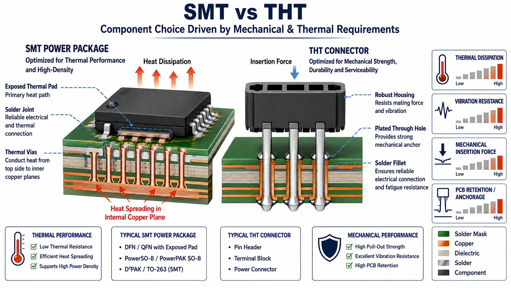
For high-vibration environments, component mounting deserves particular attention.
Examples include:
The question is not merely:
SMT or THT?
It is:
How will the component, solder joint, PCB and mechanical structure respond to the expected mechanical environment?
Potential considerations include:
23. Inspection Differences
SMT and THT also create different inspection requirements.
SMT inspection can involve:
THT inspection can involve:
X-ray becomes particularly useful for hidden solder joints such as certain BGA packages and some through-hole structures where joint visibility is limited.
24. Rework and Repair
Rework complexity varies by component.
Large THT components can sometimes be easier to manually remove and replace.
Very small SMT components can require:
BGA rework is substantially more specialized because the solder joints are hidden beneath the package.
Therefore, the rework strategy should be considered during product design.
25. PCB Layout Implications
Assembly technology should be considered before PCB layout is finalized.
For SMT, engineers should consider:
For THT:
This is where DFM/DFA becomes particularly valuable.
26. Component Orientation Matters
On an SMT board, orientation can influence:
For example, asymmetric thermal environments around a small passive can contribute to uneven solder melting and tombstoning.
Good layout practices reduce these risks.
27. THT Component Placement Matters Too
A THT component may be electrically correct but difficult to manufacture if:
Therefore, THT components need their own DFA considerations.
28. When SMT Is Usually the Better Choice
SMT is generally well suited when the design prioritizes:
High component density
Large numbers of components in a limited area.
Compact product size
Portable or space-constrained electronics.
Automated production
High repeatability and machine placement.
High-volume production
Where automation can distribute setup and process costs across larger quantities.
Fine-pitch electronics
Modern IC packages and dense digital circuitry.
Double-sided assembly
When both PCB surfaces need components.
29. When THT Is Usually the Better Choice
THT can be advantageous when the component requires:
High mechanical retention
Connectors and mechanically stressed components.
Large physical structures
Transformers, relays and certain power components.
Repeated mating
Interfaces subjected to repeated insertion/removal.
Specific legacy components
Some established designs may depend on THT packages.
Specialized electrical requirements
Where the available THT component provides the appropriate electrical or thermal characteristics.
30. When Mixed Technology Is the Best Choice
Mixed technology is often the most practical solution.
For example:
SMT
→ MCU→ Memory→ Sensors→ Passives→ Communication ICs
THT
→ Connectors→ Terminal blocks→ Relays→ Large transformers
This allows each component to use the mounting method most appropriate to its requirements.
31. Mixed Technology Requires Process Planning
A mixed-technology PCBA requires deliberate process sequencing.
A possible flow could be:
SMT side A
↓
Reflow
↓
SMT side B
↓
Reflow
↓
THT insertion
↓
Selective soldering
↓
Inspection
↓
Functional testing
The exact process depends on board architecture and component selection.
32. SMT vs THT Decision Matrix
| Engineering Factor | SMT | THT |
|---|---|---|
| Component density | Excellent | Lower |
| Miniaturization | Excellent | Limited |
| Automated placement | Excellent | Depends on component/process |
| Double-sided PCB | Highly suitable | More restrictive |
| Fine-pitch ICs | Excellent | Generally unsuitable |
| Mechanical retention | Moderate | Strong for suitable components |
| Large connectors | Available but application-dependent | Often advantageous |
| High-volume automation | Excellent | Good for suitable processes |
| Manual assembly | Possible | Often straightforward |
| Rework | Can be specialized | Often easier for larger components |
| PCB drilling requirement | Generally lower | Required for component leads |
| High-density routing | Highly suitable | Can consume routing area |
| Mixed assembly | Excellent | Excellent |
| Thermal design | Package-dependent | Package-dependent |
| Best application | Dense electronic circuitry | Mechanically demanding components |
The table should not be interpreted as an absolute ranking.
The correct technology depends on the component and application.
33. The Wrong Way to Choose
Avoid decisions such as:
“Use SMT because it is modern.”
or:
“Use THT because it is more reliable.”
Neither statement is sufficiently engineering-driven.
Instead, evaluate:
Electrical requirement
Mechanical requirement
Thermal requirement
PCB constraints
Manufacturing process
Production volume
Supply availability
Lifecycle requirements
34. SMT vs THT and Global Sourcing
Assembly technology can also influence sourcing.
SMT components are often available across broad global component ecosystems.
But specialized components can introduce:
The component-selection decision should therefore consider both:
technical suitability
and
supply-chain suitability.
This connects directly to BOM optimization and component lifecycle management.
35. Design for Assembly Before the RFQ
One of the most effective opportunities to control assembly cost and risk is before the PCB is released for manufacturing quotation.
An engineering review can evaluate:
This can identify avoidable manufacturing complexity before it becomes embedded in the design.
36. What Procurement Should Ask the Manufacturer
When comparing assembly suppliers, procurement should ask:
1. Can the supplier support both SMT and THT?
2. Can they handle mixed-technology boards?
3. What THT processes are available?
4. What SMT packages can be handled reliably?
5. What inspection processes are available?
6. Can they perform DFM/DFA review?
7. How are special components handled?
8. How are engineering changes controlled?
These questions reveal much more about manufacturing capability than simply asking for a per-board assembly price.
37. What Engineers Should Provide
For an accurate SMT/THT manufacturing assessment, the manufacturing package should ideally include:
Clear manufacturing data reduces ambiguity during quotation and NPI.
38. A Practical SMT/THT Selection Workflow
Use this sequence:
Step 1 — Identify the component function
↓
Step 2 — Determine electrical requirements
↓
Step 3 — Determine mechanical requirements
↓
Step 4 — Determine thermal requirements
↓
Step 5 — Evaluate available package options
↓
Step 6 — Evaluate PCB layout implications
↓
Step 7 — Evaluate assembly process
↓
Step 8 — Evaluate sourcing and lifecycle
↓
Step 9 — Review DFM/DFA
↓
Step 10 — Freeze the manufacturing approach
This is more robust than choosing mounting technology based purely on component availability.
39. Common SMT/THT Design Mistakes
Mistake 1 — Using THT Where SMT Would Simplify a Dense Design
This can unnecessarily consume board area and routing resources.
Mistake 2 — Using SMT for a Mechanically Stressed Connector
The mounting technology may not provide the desired mechanical robustness.
Mistake 3 — Choosing the Smallest SMT Package
Smaller does not automatically mean better manufacturability.
Mistake 4 — Ignoring Rework
Highly dense assemblies can make field or factory rework difficult.
Mistake 5 — Ignoring Soldering Process During Layout
A design may be electrically correct but difficult to solder reliably.
Mistake 6 — Treating THT as Automatically Manual
THT can be integrated into automated or semi-automated processes.
Mistake 7 — Ignoring Mixed-Technology Process Sequencing
SMT and THT should be considered as one manufacturing flow.
Mistake 8 — Selecting Components Without Lifecycle Considerations
A package may be technically suitable but commercially vulnerable.
40. A Practical Design Checklist
Before finalizing the PCB assembly technology:
☐ SMT/THT requirement evaluated per component☐ Component package selected based on electrical requirements☐ Mechanical loading evaluated☐ Thermal requirements evaluated☐ PCB area evaluated☐ Routing impact evaluated☐ THT hole requirements reviewed☐ SMT component spacing reviewed☐ Reflow process considered☐ Wave/selective soldering considered where required☐ Mixed-technology sequence defined☐ Inspection requirements considered☐ Rework accessibility considered☐ Component availability checked☐ Lifecycle risk checked☐ DFM/DFA review completed☐ Manufacturing package prepared
41. QUADRIONIX Perspective
For a PCB assembly project, the objective should not be to force every component into one assembly technology.
The more practical engineering approach is to evaluate the complete PCBA:
Component Selection
Is the selected package appropriate for its function?
PCB Layout
Does the mounting technology support routing density and thermal requirements?
Manufacturing
Can the selected components be assembled using a controlled and repeatable process?
Mechanical Requirements
Do connectors and mechanically stressed components have sufficient retention?
Supply Chain
Are the selected components commercially viable and appropriately sourced?
Production
Does the SMT/THT combination support the required production volume and quality controls?
This approach allows the assembly process to follow the engineering requirements of the product, rather than forcing the product around a manufacturing preference.
42. Final Takeaways
1. SMT is not automatically better than THT.
They solve different engineering problems.
2. SMT is ideal for density and automation.
It is particularly well suited to modern high-density electronics.
3. THT remains valuable for mechanical and specialized requirements.
Connectors, relays, transformers and mechanically stressed components are common examples.
4. Mixed technology is often the optimal solution.
Modern PCBAs frequently combine SMT and THT.
5. Package selection affects manufacturing.
Component package decisions influence PCB area, routing, stencil design, placement and inspection.
6. Reliability depends on the application and process.
Neither SMT nor THT is universally more reliable.
7. Thermal and mechanical requirements matter.
Mounting technology should be selected alongside electrical requirements.
8. Assembly technology affects cost.
But cost depends on volume, component count, process requirements, setup, testing, rework and manufacturing complexity.
9. DFM/DFA should happen before production.
Manufacturing constraints are easier and cheaper to address during design.
10. The right question is not SMT vs THT.
The right question is:
Which mounting technology gives this component and this product the best balance of electrical performance, mechanical robustness, manufacturability, cost and supply-chain resilience?
43. Conclusion
SMT and THT are not competing technologies in the simplistic sense.
They are two different manufacturing approaches that can coexist within the same electronic product.
SMT provides the density, miniaturization and automation required by much of today's electronics.
THT continues to provide valuable mechanical and application-specific advantages where component geometry, mechanical loading or specialized requirements demand it.
For many industrial and commercial PCBAs, the most effective solution is therefore a carefully engineered combination of SMT and THT.
The decision should begin with the component's function and the product's requirements—not with an assumption that one technology is universally cheaper, stronger or better.
For engineers and sourcing teams, that distinction matters.
A well-designed PCBA is not simply one that works electrically.
It is one that can be manufactured repeatedly, inspected effectively, sourced reliably, supported throughout its lifecycle and produced at a commercially viable cost.
That is where SMT/THT decisions become part of the broader DFM, DFA, BOM and supply-chain engineering strategy.
Ready to manufacture your electronics project?
Upload your Gerber files & BOM for automated DFM review, engineering feedback, and guaranteed delivery timelines.